Satellite Power Systems
The Basics
Satellite power modules are widely known as electrical power systems, or EPS. If you are purchasing Cubesat components as a kit, the EPS will come as a self contained unit, with outputs for voltage bus distribution and battery connnections. The EPS can be broken down conceptually into four smaller blocks. They are the power sources, the energy storage, the power distribution, and the Power Regulation and Control modules.
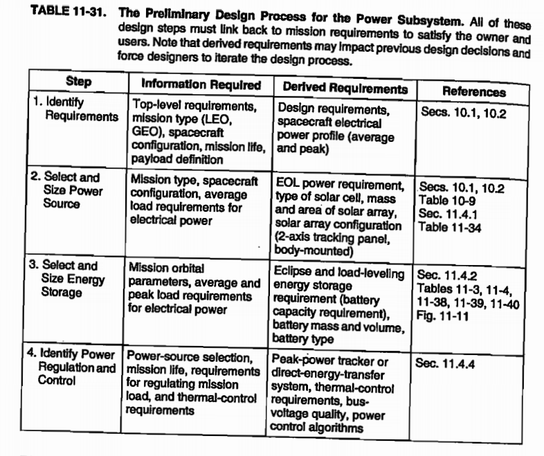
For those interested in designing their own power system, a table of the design steps can be found below courtesy of Space Mission Analysis by Wiley Larson.

Power Sources
There are many power sources available to the budding satellite designer. One might find useful applications for nuclear generators (RTGs), or regenerative fuel cells. That being said, most all satellites use photovoltaic cells. When it comes to power generation, this is the one important component you should know. The solar cells are managed via a peak power tracker or PPT unit which is discussed in the [Power Distribution] section.
Energy Storage
Most satellites store their power through a set of primary and secondary batteries. One can find a table of industry standard batteries and their characteristics below.


Power Distribution
It is typical to single a single power distribution system (PDS) in smaller satellites. In larger satellites it is not uncommon to have multiple distribution systems for collections of components. Typically a distribution bus will contain rails of 5v, and 3.3v for Cubesats. For special applications and different desired rail voltages, a modified EPS may be required. This is the critical module that handles voltage protection, isolation, and fault detection within the power block.
The PDS also typically contains the Peak Power Tracking, PPT module. The PPT monitors the solar panels and places the appropriate load resistance across the solar panel terminals in order to draw the maximum amount of power from them. Solar panels have a non-linear IV curve, which means their power output changes across loads and voltages. As the sunlight changes the voltage, the PPT adjusts the load to match.
Solar cell operating characteristics graph. Caption: the PPT keeps the solar pannels operating along the center line of peak performance.
Common Power values for Cubesats in Industry
| Storage: | ||
| Pumpkin battery pack | 40Wh | |
| Optical Payload: | ||
| Nasa's Lunar Cubesat | 10W | |
| MIT Free-Space | 15W | |
| Solar panel Production | ||
| Nasa's Lunar Cubesat | 50W | |
| CubeSatShop | 2.3W per 1U (translates to 48W for similar size of Lunar Cubesat) |
Resources to Learn More
MIT open courseware. Class on how to build a satellite. Very useful information